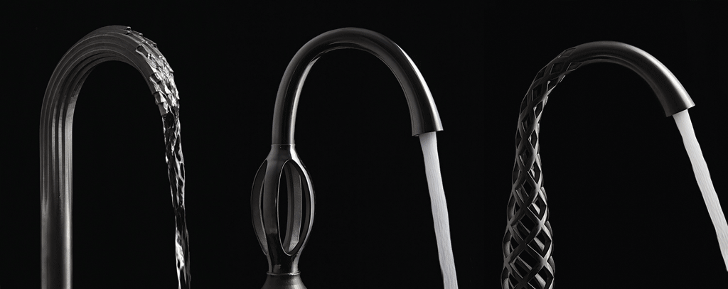
Last year American Standard announced the availability of a line of metal 3D printed faucets. Not only was American Standard using cutting edge technology to fabricate a mostly consumer-level product, but they did so with beautiful results. Of all the 3D printed products I’ve come across, none showcased the future potential of additive manufacturing to the degree American Standard did with these offerings.
Leading the effort was Vice President of Design and friend, Jean-Jacques L’Henaff. Fortunately for me, Jean-Jacques and I had been colleagues at Intelligent Product Solutions, so I had an opportunity to go to the source for some questions I had about the development of these faucets.
Below is my Q&A with Jean-Jacques, which I hope is of interest to those of you closely following the rise of 3D printing.
–
CSJ: Before we get into the details of the American Standard DXV project, can you briefly share your background and your prior experiences using additive manufacturing – 3D printing – technology?
JJL: I am a trained Industrial Designer with a background that spans from private aircraft interiors to consumer electronics. I have been using 3D printing – SLA and SLS mostly – for twenty years, but only for prototyping purposes.
CSJ: You mentioned in a previous exchange that one of the challenges from a traditional industrial design perspective was to “design something one could not make“. For both the industrial designers and makers out there, could you elaborate on your comment?
JJL: When you design an object that will be produced using 3D printing, you are designing without the conventional constrains of manufacturing: draft angles, deep cavities, consistent wall thicknesses, etc. When we started this project, we tried to push as far as we could to find the limits of this new technology – and we did find some! The constrains inherent to DMLS in particular are real, but, still, the level of freedom offered to the designers has no precedent.
CSJ: In comparison to your team’s typical development methodology, did the industrial design process itself change, and if so, in what way?
JJL: We tried not to imitate the approach we follow when designing a conventional faucet using gravity or die casting. Our third design – Shadowbrook – was the most interesting: we first designed the water, then went back to create the faucet.
CSJ: Aside from the obvious need to finish especially complex geometries, would you say fabricating production parts using an additive manufacturing process generally requires more or less labor than traditionally manufactured product? In other words, if one of your traditionally manufactured faucets were transitioned to a metal additive process, would it inherently require more finishing?
JJL: Not necessarily – it mostly depends on how you design it and the intended final finish. A conventional faucet requires polishing – by hand or robot – then plating, which is a multi-stage process. Our 3D printed faucets require breaking the support structures, grinding their traces out, and sand blasting. We decided to go one step further and have an artisan hand finish each of them by giving them what we call a “butler finish.” It mimics the silverware finish left by decades of having the butler shine them… This part takes much longer than our conventional process! But we are investigating various chemical finishes than would eliminate these steps.
CSJ: Did your team encounter any difficulties ensuring tight tolerance areas (e.g. sealing geometry, screw threads, etc.) met American Standard’s requirements?
JJL: All functional surfaces are machined after the printing and cleaning process. Some areas indeed have threads or create seals, and 3D printing today can not achieve the level of tolerance and surface finish required.
CSJ: Can you provide some technical details regarding:
a. which 3D software(s) was used to generate the final industrial design intent?
Pro-E
b. whether or not a haptic interface was utilized?
No
c. whether or not any additional software was used to manipulate or repair a mesh, and if so, which software?
None
d. whether other kinds of analysis software besides the computational fluid dynamic solver were used (e.g. an FEA application)?
No
e. whether or not textures were incorporated directly into the 3D data or were part of the post-fab process (perhaps specified in a CMF document), or both?
The only textures are applied by hand as the last step of our process, just before assembly. They are left to the discretion of the artisan. This is rather unusual for us, but the price of these products made us look at the finishes in a different light. At this level of luxury, one can expect a bespoke aspect to the product.
f. what 3D printing options and fabrication processes were considered and why the team decided on the tools which were used?
DMLS was a logical choice for this type of products.
CSJ: The press release states Selective Laser Sintering is being used; however, because “SLS” is used interchangeably with DLM and EBM, to clarify, did the team use a sintering machine and then fire the part to remove the binder and infiltrate, or did the team use a laser- or electron-beam melting process to create a completely solid part?
JJL: We used a DMLS process – more specifically an EOS printer – and decided to print directly in a stainless steel alloy called Inconel.
CSJ: How did the team evaluate the output of the CFD application? Were intermediary prototypes fabricated, a CG visualization tool used, or some other method/tool incorporated to aid in the user experience evaluation?
JJL: The team rendered the products during the design process, but the real test came when we prototyped each version. They were all printed in Somos using an SLA printer.
CSJ: In reference to the 32% decrease in water usage, was improved water usage a design goal or a happy accident, and could you explain how this improvement was determined?
JJL: This applies to the Shadowbrook: since we are not using an aerator, the amount of water flowing out of the faucet was really linked to the effect we were trying to achieve. it simply resulted in a lower water consumption.
CSJ: What surprised you during this unique project development effort?
JJL: The main surprise was to discover how early we are still in the development of this technology. Our journey was not an easy one, and we are still working out a lot of details.
CSJ: What disappointed you or didn’t meet your expectations of the technology?
JJL: There are some geometry limitations due to the heat generated during the manufacturing process.
CSJ: If you had to do this again, what if anything would you do differently?
JJL: We had to follow a path of discovery/trial and error – I would not do it in any other way.
CSJ: In general, how has the interior design community responded to these cutting edge products?
JJL: The response has been far beyond our wildest expectations. From a press and social media coverage, but also and most importantly from a commercial point of view. These products are very unique and cutting edge, and the market has been responding very strongly.
CSJ: Lastly, can we expect to see additional designs of this nature from American Standard?
JJL: Indeed!
–
My sincerest thanks to Jean-Jacques for taking time out of his schedule to answer my questions and allowing me to share that information with the public.


